If you’ve ever knelt in front of a factory’s control panel at 2 a.m., fighting erratic machine cycles or a sensor that cuts out right when you need it most, you know signal attenuation isn’t just a technical buzzword—it’s a nightmare that brings production to a screeching halt. As a control cables supplier who’s spent the last 18 years troubleshooting issues with industrial clients across North America, I’ve lost count of the times maintenance teams have come to me saying their cables worked great for a year, then suddenly started dropping signals mid-run. What I’ve learned is this: most signal attenuation problems aren’t because of cheap cables. They’re because of small, avoidable choices made during installation, design, and even routine maintenance. Today, I’m breaking down the practical, science-backed ways to cut that attenuation—no fancy, overpriced upgrades required. Control Cables

First, let’s get clear on what signal attenuation actually is, because a lot of folks throw the term around without really understanding it. Simply put, it’s the loss of signal strength as it travels along a control cable. That can look like a sensor failing to trigger on time, a PLC receiving garbled data, or even entire axes of a robotic arm freezing mid-task. The biggest culprits here aren’t just distance (though that’s a factor)—they’re interference, improper termination, and physical damage to the cable itself. I’ve seen a 50-foot run of cable work flawlessly for years, only to fail right when someone added a new motor 10 feet away, and that’s classic interference-related attenuation.
Let’s start with the easiest fix: matching your cable type to your application. A common mistake I see is engineers or maintenance teams grabbing a generic cable because it’s on the shelf, rather than picking one built for their specific environment. For example, if you’re running control cables near high-voltage power lines, variable frequency drives (VFDs), or welding equipment, you need a shielded cable—specifically one with the right kind of shielding for that environment. Not all shields are created equal. Foil shields, for instance, are great for high-frequency, low-interference environments, but they tear easily if the cable is going to be bent repeatedly, like on a robotic arm. Braided shields are more durable, but they might not block as much high-frequency interference because of the gaps between the braid strands. I recently worked with a automotive plant that was using foil-shielded cables on their welding robots; within six months, the foil had torn, and their signal loss was so bad their weld accuracy dropped by 15%. Swapping in a braided shield with a drain wire fixed the problem overnight.
Another big factor here is cable category for digital vs. analog signals. Digital signals are more resistant to attenuation, but that doesn’t mean they’re immune. Analog signals, though, are far more sensitive—even a tiny drop in signal strength can turn a 4-20mA reading into garbage data. For analog runs over 100 feet, I always recommend using twisted-pair control cables, not single-core or multi-core unshielded cables. Twisting the pairs cancels out electromagnetic interference (EMI) and radio-frequency interference (RFI) because the magnetic fields generated by the signal in each twisted wire cancel each other out. It’s basic physics, but so many people skip the twist count—look for a cable with at least 3 twists per foot for runs longer than 50 feet. We supply twisted-pair control cables that are engineered with a uniform twist rate, and the difference in signal stability is night and day compared to generic, loosely twisted cables.
Next up: proper termination and grounding of shields. This is probably the most common mistake I see, and it’s the one that causes the most preventable attenuation. A shield is only as good as its termination—if the shield isn’t connected properly at both ends, it might as well not be there. Or even worse, if it’s grounded at only one end in some environments, it can create a ground loop, which actually increases interference and signal loss. Ground loops happen when two points in a circuit have different electrical potentials, creating a small current that flows through the shield. That current messes with the signal, leading to attenuation. The rule of thumb here is: if you’re running a cable in an environment with a lot of EMI (near VFDs, motors, welding gear), ground the shield at both ends. If you’re in a low-interference environment (like a clean room or office), ground it at only one end to avoid ground loops. I can’t tell you how many clients have come to me with shielded cables that were grounded on just one end, sitting right next to a VFD, and their signal attenuation was through the roof. Taking 10 extra minutes to terminate the shield correctly fixes that every single time. Also, make sure you’re using the right connectors—crimping the shield properly isn’t enough if you’re using a cheap connector that doesn’t make full contact with the shield. We supply shielded connectors specifically designed for our control cables, and we offer free termination guides to help teams get it right.
Installation practices make or break signal attenuation, too. I’ve seen people run control cables right alongside 480V power cables, just because there was no other space in the conduit. That’s a recipe for disaster. The 600V power cables generate a strong magnetic field, which couples into the control cable and causes attenuation, especially for analog signals. The rule here is to keep control cables at least 12 inches away from power cables rated over 100V. If you have to cross power cables, cross them at a 90-degree angle—this minimizes the amount of magnetic field that couples into the control cable, because the magnetic field is strongest parallel to the power cable, weakest perpendicular. Another installation mistake: pulling cables too tight or bending them beyond their minimum bend radius. Every control cable has a specified minimum bend radius—usually 10 times the cable’s outer diameter for fixed installs, and 20 times for flexible, moving applications like robots. When you bend a cable too tight, you damage the internal conductors or the shield, which increases resistance and causes signal loss. I had a packaging plant client last year who was running control cables along a conveyor belt, bending them around a corner every 10 feet. They were using a cable with a minimum bend radius of 5 inches, but they were bending it to 2 inches. Within three months, their signal attenuation was so bad their conveyor was misaligning boxes. Swapping to a cable with a flexible construction and a minimum bend radius of 3 inches, plus adjusting the installation to follow the bend radius, fixed it in a week.
Temperature and environmental factors also contribute to signal attenuation, and they’re often overlooked. Control cables don’t just operate in perfect 70-degree factories—they’re in freezers, furnaces, outdoor equipment that sees -20F in winter and 120F in summer. Extreme temperatures can affect the conductivity of the conductors, the integrity of the insulation, and even the shield’s performance. For example, at high temperatures, copper conductors expand, which increases resistance. That resistance leads to signal loss, especially over long runs. At low temperatures, insulation can become brittle, leading to cracks that expose conductors and cause short circuits or signal dropouts. If you’re installing control cables in extreme temperatures, make sure you pick a cable rated for that environment. We supply temperature-resistant control cables with cross-linked polyethylene (XLPE) insulation, which stays flexible at low temperatures and resists melting at high temperatures, maintaining consistent conductivity and insulation properties. A food processing client of ours was running control cables in their cold storage freezers, where temperatures drop to -10F. They were using generic PVC-insulated cables, which became brittle and cracked within a year, leading to constant signal loss. Swapping to our XLPE-insulated cold-resistant cables solved that problem immediately.
Signal attenuation from length is another factor, and there’s only so much you can do about it, but there are workarounds. Every type of control cable has a maximum recommended length, beyond which signal attenuation becomes unacceptably high. For example, a generic unshielded twisted-pair cable for analog signals might have a max length of 500 feet, while a shielded version could go up to 1,000 feet. If you need longer runs, you don’t have to run a thicker cable—instead, use a signal repeater or amplifier at the midpoint of the run. These devices boost the signal strength without adding noise, so you can extend runs to 2,000 feet or more. I always recommend signal repeaters for runs over the maximum recommended length, rather than over-sizing the cable, because they’re more cost-effective and don’t take up extra space.
Routine maintenance is often the missing piece that prevents long-term attenuation problems. A lot of plants only check their control cables when something breaks, but doing regular inspections can catch issues before they turn into costly downtime. Every quarter, take a few minutes to: check for physical damage to the cable (cuts, abrasions, bends that are too tight), inspect shield terminations for corrosion or loose connections, and test signal strength with a multimeter or signal tester. Corrosion is a big one—if a connector or shield terminal is corroded, it creates high resistance, which causes signal loss. Cleaning connectors with electrical contact cleaner and tightening loose terminations is a simple fix that can add years to your cable’s life. I had a chemical plant client last year who was experiencing intermittent signal loss on their level sensors. It turned out the shield terminals on their control cables were corroded from exposure to chemical fumes. A quick cleaning and re-termination of the shields fixed the issue, and they didn’t have to replace any cables.
Now, let’s talk about common myths that I hear all the time, because misinformation can lead to even more attenuation. The first myth is: “A more expensive cable means no attenuation.” That’s not true. A high-quality cable is important, but if you install it wrong, terminate it poorly, or run it near power cables, it will still have signal loss. The second myth is: “Twisting cables is just for show.” No—twisting directly reduces EMI and RFI, and the twist rate matters. The third myth is: “All shields work the same.” As I mentioned earlier, foil vs. braided shields have different use cases, and choosing the wrong one will lead to attenuation in the wrong environment.
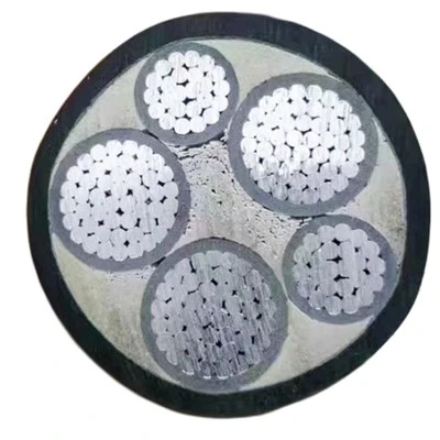
Aluminum Alloy Cable At the end of the day, reducing signal attenuation in control cables isn’t rocket science—it’s about making intentional choices when selecting cables, installing them correctly, maintaining them regularly, and understanding the science behind how signals travel. As a control cables supplier, I’ve spent decades testing, refining, and supporting products that solve real-world attenuation problems for industrial, automotive, food and beverage, and commercial clients. If you’re dealing with erratic signals, frequent downtime, or signal loss that’s hurting your production, I’d love to help you figure out the right solution for your specific needs. Whether you need recommendations for the right cable type, guidance on termination and installation, or custom solutions for your unique environment, we’re here to support you. Don’t let signal attenuation hold your operations back—reach out today to connect with our team to discuss your control cable needs.
References
- Bolt, R. (2012). Electromagnetic Compatibility Handbook. Wiley-IEEE Press.
- International Electrotechnical Commission (IEC). (2018). IEC 60227: Insulated cables for rated voltages up to and including 450/750 V.
- American National Standards Institute (ANSI). (2020). ANSI/TIA-568-C.2: Balanced Twisted-Pair Telecommunications Cabling and Components Standard.
- Smith, J. D. (2019). Industrial Control Cables: Design, Installation, and Maintenance. Industrial Press.
Hebei Fengbo Electrical Equipment Co., Ltd.
Address: No.100 meters south, East Ring Road & Wei’er Road intersection, Huang’erying East Village, Jiajiakou Town, Ningjin County, Xingtai City, Hebei Province, China
E-mail: fonbocable@gmail.com
WebSite: https://www.fonbocable.com/
